 Networks: GPON FTTX and XGSPON FTTX Systems")
Published: April 27, 2026 By: Rungrueang Huanraluek
| Item | GPON | XGSPON |
| Downstream Rate | 2.5 Gbps | 10 Gbps |
| Upstream Rate | 1.25 Gbps | 10 Gbps |
| Max Split Ratio | 1:128 | 1:256 |
| Max Transmission Distance | 60 km | 60 km |
2. SFP Module Types, Transmit Power, and Receiving Capability
Different SFP module classes determine the Transmit Power and Receiver Sensitivity of the system, which directly affects the Optical Link Budget calculation. Basic details for each system are as follows:
| Module Type | Tx Power (dBm) | Rx Sensitivity (dBm) | Max Link Budget (dB) |
| GPON B+ | +1.5 ~ +5 | -28 | 28 |
| GPON C+ | +3 ~ +7 | -32 | 32 |
| GPON C++ | +4.5 ~ +10 | -33 | 33 |
| XGSPON N1 | +2 ~ +5 | -29 | 29 |
| XGSPON N2 | +4 ~ +7 | -30 | 31 |
| XGSPON E1 | +6 ~ +9 | -30 | 33 |
(1) Fiber Optic Loss: Based on the International Telecommunication Union ITU-T G.652 standard (G.652D Single-Mode Fiber). Generally, for system design, a loss value of 0.4 dB/km should be allowed for a safe Link Budget calculation. Cable loss varies by wavelength as follows:
| Fiber Optic Loss Table (Unit: dB/km) | |||||
| Fiber Type | 1310 nm | 1383 nm | 1490 nm | 1550 nm | 1625 nm |
| G.652.D | 0.35 | 0.31 | 0.25 | 0.22 | 0.24 |
| G.653 | 0.35 | - | - | 0.25 | - |
| G.654 | - | - | - | 0.17 | 0.19 |
| G.655 | 0.35 | - | - | 0.22 | 0.24 |
| G.657.A1 | 0.35 | 0.31 | 0.25 | 0.22 | 0.24 |
| G.657.A2 | 0.35 | 0.31 | 0.25 | 0.22 | 0.24 |
| G.657.B2 | 0.35 | - | 0.25 | 0.22 | 0.24 |
| G.657.B3 | 0.35 | - | 0.25 | 0.22 | 0.24 |
(2) Splitter Loss: Optical splitters are vital in PON networks, and loss increases as the split ratio increases. PLC Splitter loss values for calculation are as follows:
| Splitter Loss Table | ||
| Split Ratio | Theoretical Loss (dB) | Actual Loss Range (dB) |
| 1:2 | ~3 | 3.3 ~ 3.8 |
| 1:4 | ~6 | 6.5 ~ 7.2 |
| 1:8 | ~9 | 10.2 ~ 10.8 |
| 1:16 | ~12 | 13.5 ~ 14.5 |
| 1:32 | ~15 | 16.5 ~ 17.5 |
| 1:64 | ~18 | 19.5 ~ 21.0 |
| 1:128 | ~21 | 22.5 ~ 24.5 |
(3) Fiber Optic Connector Loss: Each connector results in an approximate loss of 0.2 ~ 0.5 dB. It is recommended to calculate at 0.5 dB per connector.
(4) Bend Loss: Bending fiber optics with a radius that is too small causes loss (Micro-bending Loss) ranging from 0.1 ~ 3 dB. Recommended bend radii must be greater than 30 mm (Standard fiber) or greater than 10 mm (Bend-insensitive fiber). It is recommended to calculate at 0.5 dB per route.
(5) Splice Loss: In practice, this value ranges from 0-0.1 dB per splice point. It is recommended to calculate at 0.1 dB for every splice point.
(6) Safety Margin Loss: Generally, a 3 dB safety margin is allowed for aging, temperature-related loss, and other environmental factors.
Examples of Optical Link Budget Calculation
EX.1 Calculate the total loss in a GPON FTTX network using a GPON C++ SFP Module and a 1:32 PLC Splitter. The fiber optic distance from the Server Room to the furthest Guest Room is 0.5 km (0.2 km Multi-Core and 0.3 km Drop Fiber), with 5 connectors and 3 splice points.
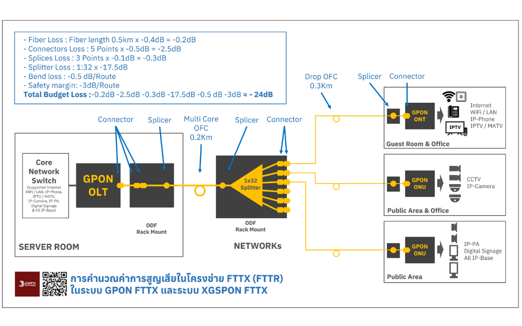
Total Budget Loss = Fiber Loss + Connectors Loss + Splices Loss + Splitter Loss + Bend loss + Safety margin
- Fiber Loss : Fiber length 0.5km x -0.4dB = -0.2dB
- Connectors Loss : 5 Points x -0.5dB = -2.5dB
- Splices Loss : 3 Points x -0.1dB = -0.3dB
- Splitter Loss : 1:32 x -17.5dB
- Bend loss : -0.5 dB/Route
- Safety margin: -3dB/Route
Total Budget Loss ≈ -24dB
GPON Class C++ SFP Module supports a Maximum Link Budget of approximately 33 dB.
From the calculation, the total network loss (Total Budget Loss) is approximately -24 dB, which is lower than the value supported by the GPON Class C++ SFP Module. Thus, there is sufficient margin, ensuring the system can operate stably and according to design standards.
EX.2 Calculate the total loss in a GPON FTTX network using a GPON C+ SFP Module and a 1:16 PLC Splitter. The fiber optic distance is 10 km, with 5 connectors and 7 splice points.
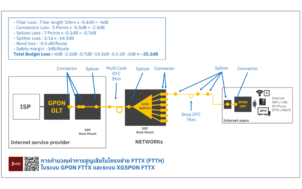
Total Budget Loss = Fiber Loss + Connectors Loss + Splices Loss + Splitter Loss + Bend loss + Safety margin
- Fiber Loss : Fiber length 10km x -0.4dB = -4dB
- Connectors Loss : 5 Points x -0.5dB = -2.5dB
- Splices Loss : 7 Points x -0.1dB = -0.7dB
- Splitter Loss : 1:16 x -14.5dB
- Bend loss : -0.5 dB/Route
- Safety margin: -3dB/Route
Total Budget Loss :-4dB -2.5dB -0.7dB -14.5dB -0.5 dB -3dB &


